Brett Reisker | Construction Management
Advisor | Dr. Somayeh Asadi
PENN STATE HERSHEY DATA CENTER
HUMMELSTOWN, PENNSYLVANIA


Figure 13
Courtesy of Holder Construction

Figure 7
Figure 8
Courtesy of Holder Construction
Courtesy of Holder Construction
Figure 2
Figure 5
Figure 4
Figure 3
Building Envelope
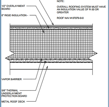

Figure 6

Controls Subcontractor
Johnson Controls

Mechanical Subcontractor
McClure Company

Electrical Subcontractor
Lighthouse Electric
BUILDING STATISTICS
General Building Data
Building Name
Location
Occupant
Occupancy Type
Size
Stories
Building Height
Project Delivery Method
Data Type
Deisgn/Precon Dates
Construction Dates
Total Project Cost (Projected)
Penn State Hershey Data Center
Hummelstown, PA
Penn State ITS/OPP
Type II-B (IBC)
46,000 SF - 10,550 SF White Space - 35,305 SF Support Space
1
30' AFF (Top of Precast) - 37.5' (Top of Screen Wall)
CM at Risk with GMP contract
1.7 MW Critical Power, Expandable to 3 MW
Tier III - Concurrently Maintainable (not formally rated)
9/2013 - 12/2014
1/15/2015 - 2/24/2016
$41,000,000
Project Team
Owner
Penn State University


Architect / Engineer
IDC Architects (a CH2M Hill Co.)

General Contractor
Holder Construction Company
Architecture
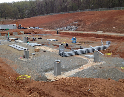
This single-story data center sits very close to the busy Penn State Hershey Medical Center in Hershey, Pennsylvania. It sits in a vacant Greenfield with a parking lot and loading dock area in front of the building (refer to Figure 1). The 46,000 SF of interior space includes 10,550 SF of data hall area for day 1 servers and day 2 expansion, a staff area consisting of offices and conference rooms, and supporting infrastructure areas including electrical and mechanical equipment rooms. There is also an exterior equipment yard for generators and transformers and there is mechanical equipment for the infrastructure rooms supported on the roof. Interior finishes include an acoustic ceiling grid system in the technology spaces and most office areas. The hallways and infrastructure spaces all have exposed ceilings and the overhead MEP is visible.
Utility ductbanks and extensions include electric, telecom, fiber, gas, storm-water, sewer, and domestic water. Other site-work includes new roadways, parking, sidewalks, guardrails, signage, bollards, and final landscaping.

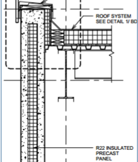
The skin of the building consists of 2 general wall types. At most of the administration areas, the façade is made up of an aluminum exterior storefront system. Below the storefront glazing is a precast stone veneer panel attached to 8” metal studs and a sheathing and vapor barrier layer (refer to Figure 2). These studs contain batt insulation. Above the storefront is a 3” insulated metal panel system attached to 8” metal studs and a sheathing and vapor barrier layer (refer to Figure 3). The wall type at the rest of the building is a 10” insulated precast wall panel that extends all the way down to the foundation (refer to Figure 4). The entire building, other than the administration area, also has a stainless steel perforated screen wall that extends above the roof (refer to Figure 5). The purpose of this is to hide the mechanical equipment that rises above the roof and is not aesthetically pleasing.
The roof uses crickets to drain storm water to the roof drains and out to the exterior storm system. The structure is sloped from the center to the West and East edges. The insulation is also tapered and sloped at 1/4” per 1’-0”. The roof system sits on metal roof deck and consists of underlayment board, 6” of rigid insulation, an overlayment board, and a white multi-ply membrane on the exterior (refer to Figure 6).
Applicable Codes
Zoning
Historical Requirements
There are no historical requirements for this building.
There are no zoning requirements for this building.
International Building Code (IBC) 2009
Pennsylvania, Uniform Construction Code 2009
Dauphin County Codes
Factory Mutual (FM)


Images Courtesy of Holder Construction
Figure 1
Construction
Penn State pushed for the development of their first data center, along with a second on the University Park Campus, due to capacity issues for computing loads. They were both designed by IDC Architects and are being managed and built by Holder Construction Company, an Atlanta based contractor who specializes in data center construction. Project construction began in January 2015 and has a projected duration of 14 months. The overall cost of the project is approximately $40.4M ($880/SF). In addition, a major goal and requirement of Penn State is to achieve LEED Certification on the project in New Construction. The goal of LEED Silver will be achieved due to an energy efficient design and sustainable construction.
The project delivery method for this project is CM at Risk. CM at Risk is becoming one of the more common types of delivery systems. This system helps Penn State save time/money, consolidate construction into one contract under the CM, choose the CM due to qualifications, receive a bonded guaranteed maximum price, and reduce risk for everyone. Penn State holds a Guaranteed Maximum Price (GMP) contract directly with the CM (Holder Construction) as well as a direct contract with the design team (IDC Architects). Holder Construction then held competitive bidding with qualified subcontractors to produce direct contracts with them. The contracts that Holder Construction holds with the subcontractors are a combination of GMP and Lump Sum. The Electrical, Mechanical (HVAC and Plumbing), and Controls/EPMS contracts are all “Team Approach” subcontractors and have GMP contacts. The subcontractors are Lighthouse, McClure, and Johnson Controls, respectively. This is appropriate because their scopes of work are a lot more than other subcontractors and a GMP contract helps reduce risk for both parties. Other contractors have Lump Sum contracts, which are more appropriate for contracts of smaller amounts. Holder Construction also has Purchased Orders for major equipment, doors/frames/hardware (DFH), and DCIM (Data Center Infrastructure Management).
The data center was built on a vacant Greenfield, so there was enough room for ample parking and material storage on-site. This was also the reason that there was only minor demolition of hardscapes towards the exterior of the site. The construction entrance splits off from Bullfrog Valley Road, and is also used as the exit to the site. Room was made for a trailer for the construction manager with a conference room, the owner, and all of the main “Team Approach” trades. Difficult site conditions include the building being designed as a “balanced site”. Even though there were 150,000 tons of dirt moved on the site, no dirt was allowed to be removed or brought to the site. Areas on-site needed to be designated for soil stockpiling when the building footprint was cut. To complicate further, an existing natural gas line feeding the hospital was located where the final electrical rooms are (most critical rooms), although believed to be elsewhere. The gas line was to be relocated prior to the start of construction (December, 2014), but was not relocated until May, 2015. This accounted for countless delays in the projects critical path.
Structural System
The sub-structure of the building is comprised of concrete footings, spread footings, stem walls, and pilasters, or piers. The footings were excavated and supported by either benching or sloping the soil. Structural fill was then added and compacted in lifts. Engineered formwork was then used and the concrete footings and the pilasters poured. The formwork was supported by kickers made from wood. The concrete was placed using a concrete pump that was located to the West of the building for easy access for the concrete trucks.
Structural steel is fastened to the concrete piers with the use of anchor bolts and base plates. The steel is comprised of W-flange beams and a mix of W-flange and HSS columns. For horizontal structural support, HSS braces are installed and welded diagonally at critical points in the system. 18 Gauge wide rib metal deck is then attached to the steel beams to form the base for the roof system. The structural steel and roof deck can be seen in Figure 7 below. The crane had 2 primary locations on the site which were the crane roads along the West and East of the building. If possible, the crane erectors would lift and install the steel straight off of the truck, but they also utilized their material laydown area right on the edge of their crane road. The construction sequencing for the structure can be seen in Figure 8 below.
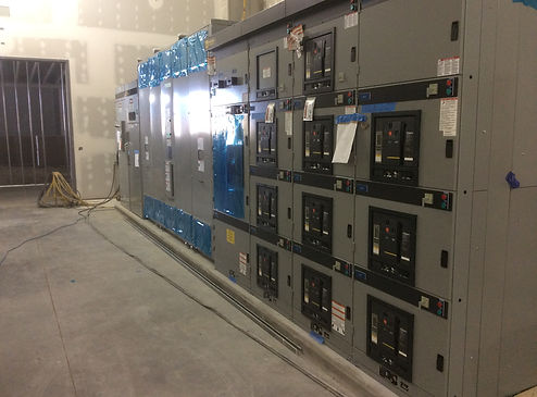
The electrical service consists of two (2) 13.8KV main feeds (A&B) from the existing Central Plant to the East of the building through an underground ductbank system. They come into the building through the equipment yard to the switches and then to the medium voltage transformers (refer to Figure 9). The power then enters the building though underground conduit (refer to Figure 10) to the main distribution switchgear (refer to Figure 11) that distributes it to different equipment throughout the building. Critical power distribution in the technology spaces is via overhead bus duct. The system is made for to support 1 MW critical power for the Day 1 construction. With this being a data center and containing sensitive information, it is imperative that the power be backed up so that there is always power running to the building. This system consists of a static UPSs (Uninterruptible Power System, 2N configuration). The UPS system will recognize if there is any interruption in the main power feed and either switch it to feed B or switch it to the backup system. The backup system consists of wet cell batteries that will keep the power on for up to 5 minutes (refer to Figure 12). This gives the two 2.5 MW generators in the equipment yard time to start-up and take over. These generators have two 7,000 G fuel tanks, which is enough to keep the building running for up to 72 hours. The generator power is recognized and distributed due to the ATS’s (Automatic Transfer Switches). There is also a 36 KW dedicated, single module house UPS used primarily for life safety, security, fire protection, and DCIM systems. Along with this is a 25 KW Life safety generator which is natural gas fed.
Electrical System
The mechanical system is also extremely important to a data center due to how much heat the data servers create. They have to constantly be cooled and these systems are backed-up using the electrical back-up system. The design tried to take advantage of the local environment and uses only outdoor ambient air for cooling purposes for 85% of the year. Each space in the building has different mechanical systems that support it. The White Space utilizes 5 AHUs, the UPS rooms uses 2 AHUs, and the office and admin area uses a packaged Indirect Evaporative Cooling with DX Trim (N+1 Configuration) in which the units are located on the rooftop (refer to Figure 13). There is also 2 makeup air units (AHUs) that supply the Data Hall and UPS rooms so that the pressure in these rooms are equalized. In the data hall a Hot Aisle Containment System contains the hot air from the servers and exhausts it through the roof.
Mechanical System
Fire Protection
There are 2 different system types of fire protection within the building. In the office and admin areas, the system is comprised of wet pipe sprinklers. In the white space, the system was designed with a pre-action (dry-pipe) sprinkler system. This is due to the sensitive electrical equipment in the data hall; the dry-pipe system does not have water in it at all times so there is not risk of leaks and damage. It requires 2 actions for the system to go off (dual-interlock). The system will trigger if the smoke detector system and the fire detector system to go off in the area. In the white space and supporting infrastructure rooms, an early warning smoke detection fire alarm system is utilized (EWSD). This system is constantly pulling in air from the area which warns the system of a fire in the quickest possible way.
The building systems are controlled using 3 different controls systems. The mechanical systems are controlled using BAS (Building Automated System). The electrical power is controlled using the EPMS, or Electrical Power Monitoring System. Cabinet level electrical circuit monitoring in the data hall is controlled with the DCIM System, or Data Center Information Management. This comprehensive system also monitors and controls all critical mechanical and electrical infrastructure components.
Controls